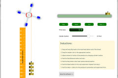
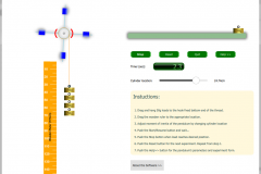
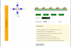
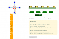
Download the simulator for Oberbeck’s pendulum from our server.
Oberbeck’s pendulum is an instrument for investigation rotational motion of rigid body. The instrument is widely used in laboratory of mechanics. The pendulum consists of pulley, four crossed sticks, and four cylinders on sticks. A thin flex wire is wrapped on the pulley. When you hang the load on the end of the wire, the pendulum begins to rotate. Angular acceleration of the Oberbeck’s pendulum depends on moment of inertia, torque and mass of loads.

Download the simulator for Oberbeck’s pendulum from our server.
The OBERBECK PENDULUM software is a simulator for Oberbeck’s pendulum. You can download the software from our server clicking here. In order to execute experiment on OBERBECK PENDULUM, you have to hang loads on the bottom end of string. Newton’s second law for rotational motion is:
$$I \frac{d \vec \omega}{dt} = \vec M \qquad \qquad (1)$$
Here $\vec M$ is net external torque, $I$ is moment of inertia of the pendulum, $\omega$ is angular speed of the pendulum.
Torque could be written as vector multiplication of radius vector and string tension $\vec T$:
$$\vec M = \vec R \times \vec T \qquad \qquad (2)$$
Newton’s second law for the load is:
$$m \vec a = m \vec g + \vec T$$
here $\vec a$ is acceleration of the load.
Scalar form of the above equation is:
$$ma = mg – T$$
From the last equation you can find $T$ as:
$$T = mg – ma = m(g – a)$$
Then we substitute this result into to below equation and obtain:
$$I \frac{d \omega}{d t} = RT=Rm(g-a) \qquad \qquad (3)$$
Substituting $d \omega / dt = a / R$ to above equation we receive:
$$I \frac{a}{R} = Rm(g-a) \qquad \qquad (4)$$
Linear acceleration of the load from Eq. 3 is:
$$ a = \frac{Rmg}{\frac{I}{R} + Rm} = \frac{mR^2}{I + mR^2} \cdot g$$
The load, initially at rest travels distance $h$ in time $t$:
$$h=\frac{at^2}{2} = \frac{mR^2}{I+mR^2} \cdot g \cdot \frac{t^2}{2}$$.
$$I=mR^2 \bigg( \frac{gt^2}{2h} – 1 \bigg) \qquad \qquad (5)$$
We can obtain moment of inertia from last equation by measuring $h$, $m$ and $t$.
Let $l_0$ and $l$ denote the stick length and pulley center to cylinder location respectively.
| # | $m \quad (kg)$ | $R \quad (m)$ | $h \quad (m)$ | $t \quad (sec)$ | $I \quad (kg \cdot m^2)$ |
| Cylinder location: $l= $ | |||||
| 1. | |||||
| 2. | |||||
| 3. | |||||
| 4. | |||||
| 5. | |||||
| $I_{mean} = $ | |||||
| # | $m \quad (kg)$ | $R \quad (m)$ | $h \quad (m)$ | $t \quad (sec)$ | $I \quad (kg \cdot m^2)$ |
| Cylinder location: $l= $ | |||||
| 1. | |||||
| 2. | |||||
| 3. | |||||
| 4. | |||||
| 5. | |||||
| $I_{mean} = $ | |||||
| # | $m \quad (kg)$ | $R \quad (m)$ | $h \quad (m)$ | $t \quad (sec)$ | $I \quad (kg \cdot m^2)$ |
| Cylinder location: $l= $ | |||||
| 1. | |||||
| 2. | |||||
| 3. | |||||
| 4. | |||||
| 5. | |||||
| $I_{mean} = $ | |||||
Here are some important parameters of the Oberbeck’s pendulum.

Download the simulator for Oberbeck’s pendulum from our server.
| Parameters | Value | |
| 1 | Stick length | $l_0=30.0cm$ |
| 1 | Stick diameter | $d_0=2.0cm$ |
| 2 | Radius of the pulley | $R=7.0cm$ |
| 2 | Mass of the pulley | $m_p=0.03kg$ |
| 2 | Mass of the cylinder | $m_{cyl}=0.2kg$ |
| 2 | Height of the cylinder | $H_{cyl}=8.0cm$ |
| 2 | Outer radius of the cylinder | $r_2=3.5cm$ |
| 2 | Inner radius of the cylinder | $r_1=1.0cm$ |
You can calculate moment of inertia using parameters shown in last table as following;
$$I = 4 \cdot I_{stick} + I_{p} + 4 \cdot I_{cyl} \qquad \qquad (6)$$
Here:
Moment of inertia of the stick:
$$I_{stick} = m_{stick} \cdot R^2 + m_{stick} \cdot l^2$$
Moment of inertia of the pulley:
$$I_p = m_p \cdot R^2$$
Moment of inertia of the cylinder:
$$I_{cyl} = \frac{1}{12} m_{cyl} (3 \cdot (r_2^2 + r_1^2) + 4h^2) + m_{cyl} \cdot l^2$$
Changing location of cylinders will lead to change moment of inertia of the cylinders.
Fill the table below and compare results from Eqn.(5) and Eqn.(6). Keep in mind that these results should be approximately same.
| # | $l (cm)$ | Moment of inertia by Eqn.(5) | Moment of inertia Eqn.(6) |
| 1 | |||
| 2 | |||
| 3 |
Download the simulator for Oberbeck’s pendulum from our server.


